
My Virginian Railway operates with separate Dispatcher and Station Operator positions, and these people must talk with each other. Each position has a small console (see the dispatcher's console and the operator's console). Originally I installed a homemade telephone system like the one crews use to call the Station Operator, but it picked up a bit of electrical interference, and the constant low-level buzz was annoying on the dispatcher's speaker (the crew system used handsets).
Nevertheless, the simple telephone system worked well for most communications, and I might use it again. Here is the schematic (PDF, 91K) if you think it might be useful on your railroad.
Friend Lance Mindheim discovered the Radio Shack no. 43-3105 wireless intercom works well as a model railroad communications system, so I bought a set. The $60 system comes with three stations, so I have a spare unit that can be used as a "scanner radio" in the crew lounge.
The only problem I had was the intercoms didn't fit my 1954 era, so I decided to see if the circuitry could be installed in the Dispatcher and Station Operator consoles. It was a cakewalk! All that's required is resoldering a few wires. The following photos and text describe the modifications.
Unplug the power cord! Remove four screws from the case bottom to separate the two halves. Remove one more screw from the center of the circuit board to free it from the case top.
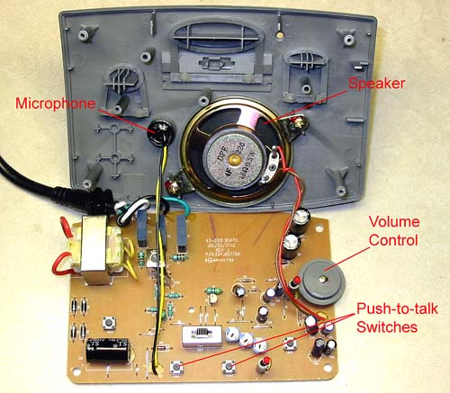
Remove the microphone and speaker. Two screws hold the speaker to the case. The microphone is held in place with a thick sticky substance, but careful pulling around the edges of the substance with needlenose pliers will eventually free it. Be careful not to pull too hard on the microphone wires - work on the sticky stuff.
All the circuitry is on one circuit board, with wires to the microphone and speaker mounted in the case. The volume control on the circuit board also contains the on-off switch. The tiny push-to-talk switches are actuated by the large plastic oval at the top of the photo.
I wanted the volume control to be on the console panel, so it had to be completely replaced. There's no need for this if your arrangement can use the existing control. The volume control attaches at five points. Using a "solder sucker" (piston vacuum tool) or desoldering braid, remove the solder from these points and take off the control.
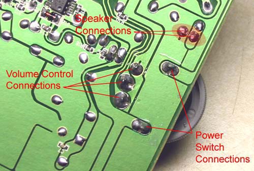
Likewise, unsolder the speaker wires if you need them longer. Replace them with common 24 gauge hookup wire, soldering to the speaker terminals and the circuit board pads. It doesn't matter which wire goes to which terminal.
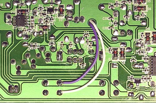
This photo shows how the replacement (external) volume control is wired, along with the power switch jumper wire and the lengthened speaker wires.
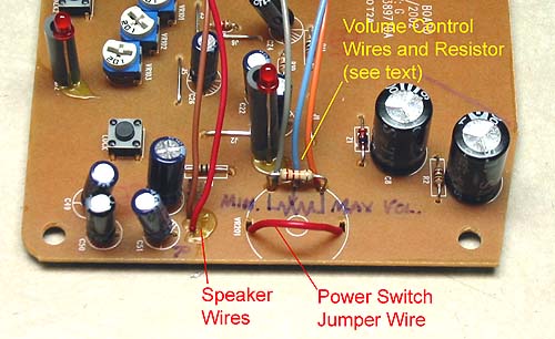
The volume control is a 10K Ohm potentiometer with a "wiper" (center terminal) that slides between the two outer terminals when the knob is turned, changing the resistance as it goes. In this photo the blue wire connects to the wiper and the gray and orange wires connect to the outer terminals. If your volume control operates backward when done, reverse the gray and orange wires on the potentiometer.
I had only a 25K Ohm potentiometer, so I needed a parallel resistor to reduce the resistance of mine to about 10K. That's what the 22K resistor shown above is for. In fact, the speaker volume really is too loud, so I'll use a 10K or 6.8K resistor to reduce it ever further.
This intercom's transformer is always powered when the line cord is plugged into a household receptacle. The volume control switch controls only the output of the transformer to the circuitry. I decided to bypass the switch (red wire above) so the intercom powers-up as soon as it's plugged in.
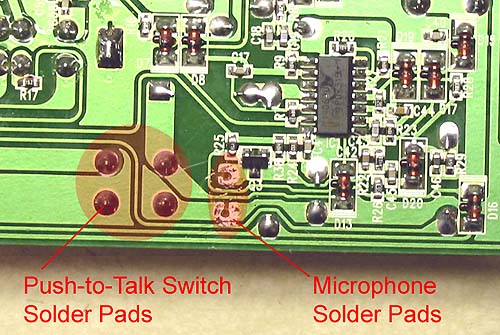
The microphone connects to the two solder pads indicated above. Replace the wires with longer ones if needed, and be sure to connect the yellow and black wires to the same pads; reversing them will prevent the microphone from working (and may damage it).
I use a foot switch to activate the "talk" function, so the Dispatcher and Station Operator have both hands free. Therefore, I needed two wires to connect the intercom circuit board with the (SPST, normally-open) foot switch.
The intercom's two push-to-talk switches should remain soldered to the circuit board, as they have internal connections needed for correct operation. I soldered two wires to one of the switch's terminals as shown above. It doesn't matter which set of terminals you use, but the wires should be attached to the two wide circuit paths, not both to the same path.
Note: The photo shows the wires running through a hole in the circuit board. After the photo was shot, I decided to re-install the board in the case, and this hole is needed for that. The wires actually run beneath the circuit board and out a hole cut in the back of the case.
Here is the intercom circuit board installed in the Dispatcher's console. I simply glued the case to the console with several dabs of Goop.
I didn't use the intercom's speaker because a large speaker was already installed in the console. The volume control is below the speaker, mounted through a hole in the front panel. The external microphone isn't shown here because I need to make some type of 1954-appropriate housing for it.
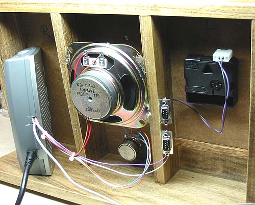
The connectors in the righthand section are for the foot switch and to get the fast clock signals from the Station Operator's console. The fast clock movement also can be seen in this area.
This was an easy project. The intercom provides the microphone sensitivity and speaker volume necessary for a loudspeaker-based telephone system.