
Scroll down to read about the new turntable drive.
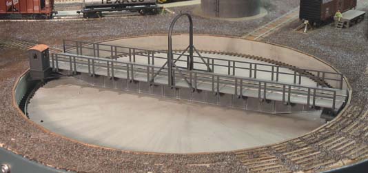
The Glen Lyn engine terminal boasts a 105-foot turntable manufactured by Custom Model Railroads (CMR). This kit features laser-cut acrylic parts and actual ball-bearing bridge wheels. At $176, it's somewhat expensive, and it certainly isn't a shake-the-box kit, but it builds into a solid, nice-looking turntable. I built the turntable according to the instructions, but made a few modifications, described below.
The turntable is designed for bridge track power to be fed through the metal wheels rolling on the pit rail. One rail is connected to the wheels at one end of the bridge and the other rail at the other end. The pit rail is split into two halves, and each half is wired to one side of the track power.
I did things a bit differently. Here's why....
It's necessary to reverse the polarity on the bridge track as it rotates 180 degrees, or an electrical short-circuit will occur when driving a locomotive off the bridge. CMR designed the turntable to automatically reverse the bridge polarity using the split pit rail. However, to achieve this, additional gaps are cut to produce two four-inch (10cm) lengths of unpowered rail. As the bridge turns, the wheels enter these unpowered sections, preventing a short-circuit that would occur if a wheel contacted both halves of the pit rail.
Unfortunately, this kills the power to the bridge, causing locomotive lights to turn off or sound to stop - sometimes for several seconds. To me, this is highly unrealistic. So I installed a DCC automatic polarity reverser (I used the one from Model Rectifier, but other vendors offer them too). Now, when the locomotive wheels span the gap between the bridge and the lead track, the reverser instantly switches the polarity. The lights don't flicker, and the sound isn't interrupted.
I didn't cut the extra gaps in the pit rail, so now the entire circle is wired to one side of the track power; all four bridge wheels pick up power for one bridge rail. I drilled a shallow hole in the bronze center bearing, and soldered a wire to the other side of the track power. The second bridge rail is connected to this metal shaft.
I was very disappointed with the lack of bridge detail in this kit. The only details are 1/16" thick tapered "ribs" to be glued at intervals on the sides. To me, five-inch-thick ribs just didn't cut the mustard. I wanted more and finer detail. Fortunately, I had a couple of Central Valley 72-foot double-track plate girder bridge kits, and a little kitbashing yielded nicely-detailed "skins" that will be applied to the sides of the turntable bridge.
I also added a control shack from a Walther's turntable, instead of the plain laser-cut structure in the CMR kit. And I modified the arch over the turntable, since Virginian's turntables had curved I-beam arches. It was easy to splice Evergreen styrene shapes with some of the CMR arch pieces. You can see these detail in the photo above.
After trying two different motors - the last of which was way too fast - I decided to build my own worm gear drive. The recent purchase of a small metal lathe and a milling machine made this easy, and it was a satisfying project.
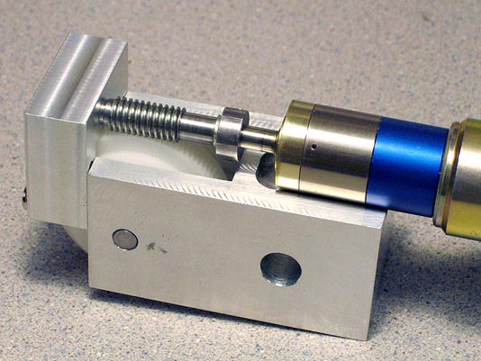
The worm started life as a 3/8"-16 machine bolt which I turned down to leave a round head and two sections of thread. In one section I cut crosswise slots to convert the threads into teeth for cutting the worm wheel. Cutting a true worm wheel uses a process called "hobbing," where the worm teeth themselves cut into the worm wheel. This results in a perfect fit, with no slop or backlash. Afterward, the cutting section is cut off the worm, leaving the "real" worm.
Here's a picture of the worm wheel ready to be hobbed by the slotted portion of the worm thread.
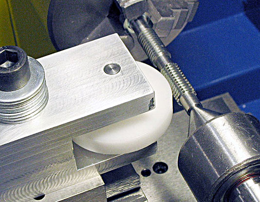
The worm wheel is made of Delrin, which is a pleasure to machine. It's soft enough for the mild steel worm teeth to cut into, but dimensionally stable, so it holds the final shape very well. (I could have used brass or aluminum for the worm wheel, but I'd need much harder material for the worm to cut the teeth.)
The mounting bracket was machined from a solid piece of aluminum. This bracket first was used to hold the worm wheel while hobbing it (see the photo above). The threading action causes the worm wheel to rotate, so it needs a sturdy support and a free-moving shaft.) After the hobbing was done, I finished machining the bracket to its final shape.
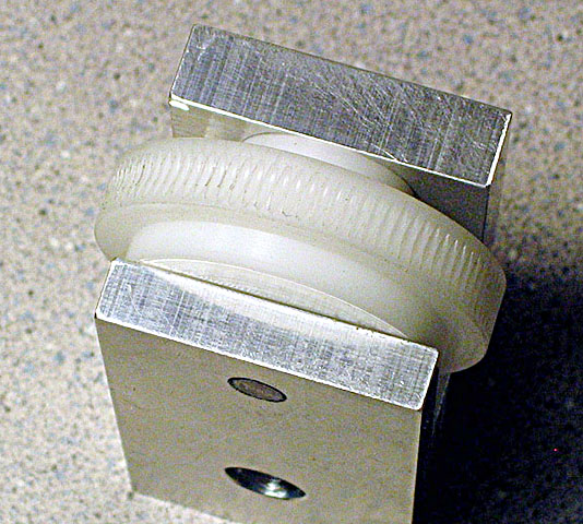
Here is the finished worm wheel in the aluminum bracket.
A second piece of aluminum was machined to fasten to the main bracket and support the end of the worm shaft. Once everything was aligned, the motor was glued in place with Goop adhesive.
The motor was a lucky find. I made a trip to the local dump to drop off some household trash, and an object in a Dumpster caught my eye. When I fished it out of, and it turned out to be a heavy-duty lead screw mechanism with a German gearhead motor attached! The lead screw was damaged, but the motor was in perfect condition.
Aligning the Glen Lyn turntable is done by eye, and crews can walk around to view either end of the bridge. To allow easy control from any position, I built a tethered hand control from a Radio Shack no. 270-409 battery holder. Even though this plastic case has compartments and electrical contacts for four AA batteries, it is easy to modify and is smaller than a typical "project case." Another nice feature is that it comes with a SPDT slide switch - exactly what is needed for the turntable control.
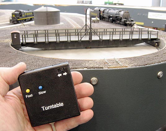
The slide switch sets the direction of rotation. Pressing the left button runs the turntable at top speed (fairly slow, thanks to the gearhead motor and my 95-tooth worm gear). The right button operates the turntable at about one-quarter of top speed, for final alignment with the lead tracks. I used switches from an old computer keyboard for these pushbuttons; they're the mechanical type, with actual metal contacts inside. The yellow and blue balls are large map pins inserted into the switch shank.
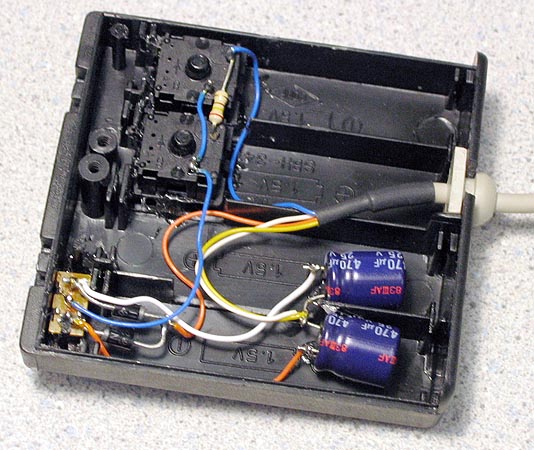
Here is what the circuit looks like inside the case. The components consist of two diodes, two capacitors, one resistor, and the slide switch. It connects to the DCC track power, and one diode/capacitor set produces positive voltage while the other set produces negative voltage. (Using positive and negative voltages obviates the need for a DPDT reversing switch.) One button connects full voltage directly to the motor for top speed, and the other button drops the voltage through a 240 Ohm resistor for slower speed.
There are going to be some happy hostlers in the Glen Lyn yard with the new turntable drive and hand control!